Smart Home Thermostat-University
What?
Designing and building a smart home thermostat using an ESP32 microcontroller, capable of controlling a fan and heater based on thermistor sensor readings, with the ability to override settings via voice commands or wireless control through a web interface
How?
Hardware
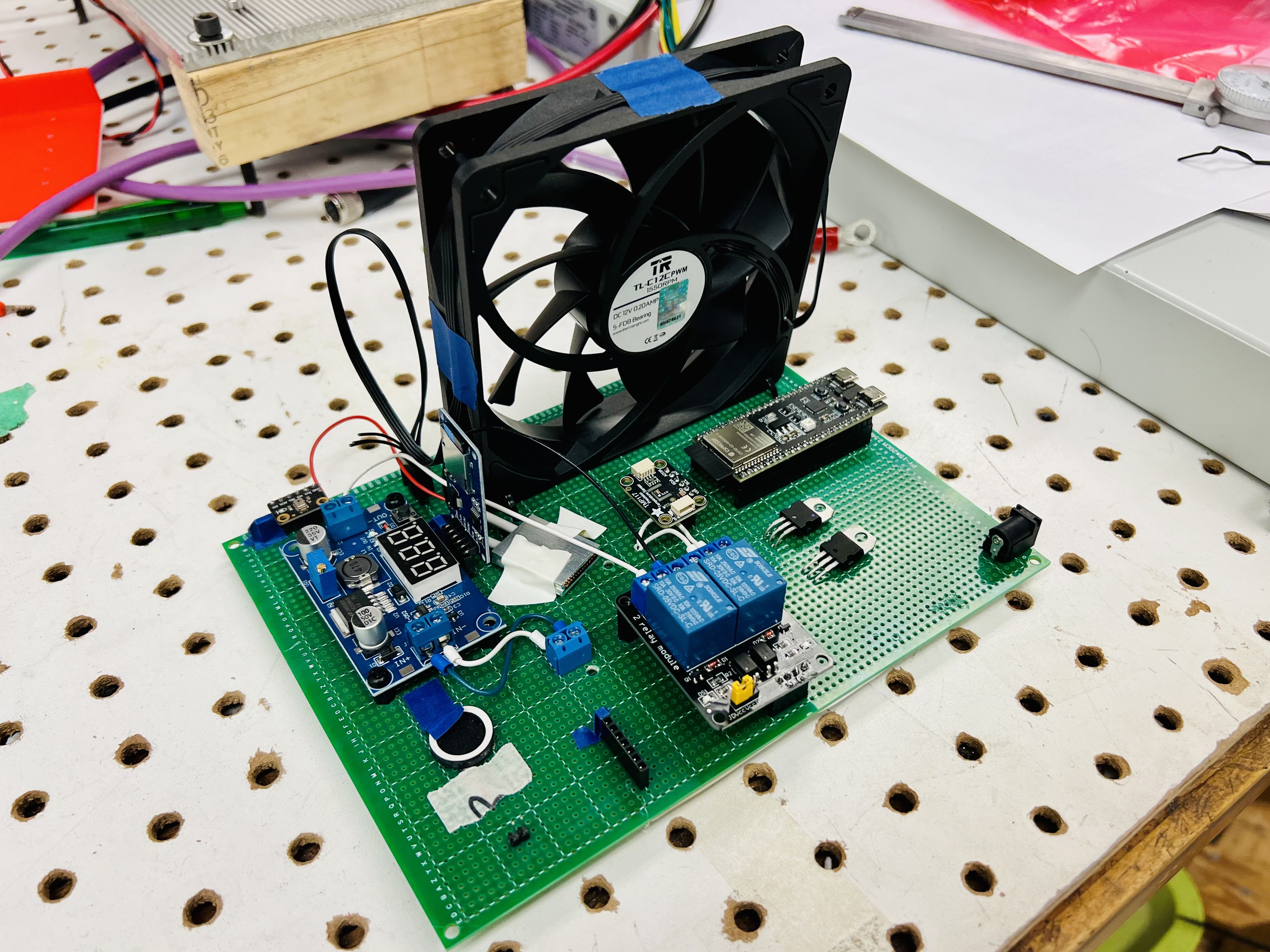
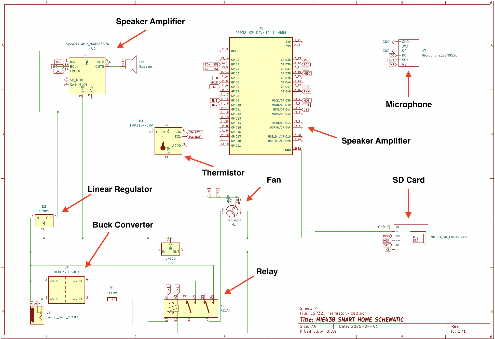
- The system was built around an ESP32 microcontroller, which interfaced with all peripheral components.
- Power Management:
- A 12V external power supply was connected via a barrel jack.
- Voltage regulators stepped down voltage for 5V components.
- A buck converter was used to supply higher current to power-demanding components such as the heater.
- Relay Control:
- A 2-channel relay module was used to switch the fan and heater ON/OFF based on user-defined temperature limits.
- Communication Protocols:
- I2C: Used for interfacing with the temperature sensor.
- I2S: Used for driving the speaker amplifier.
- SPI: Connected to the microSD card reader.
- Serial: Used to control relays.
- PWM: Implemented for controlling fan speed (RPM).
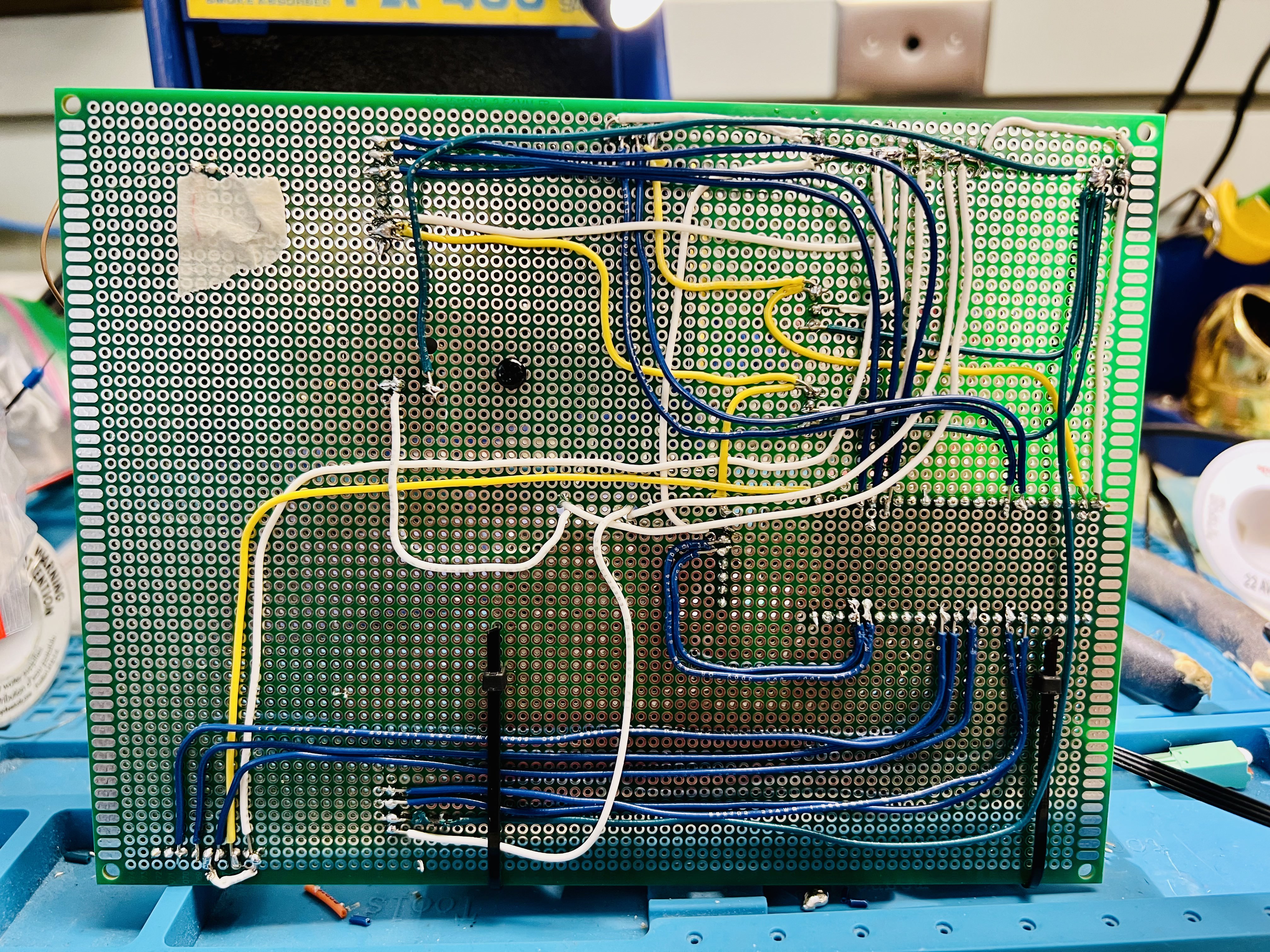
- All components were soldered onto a prototyping board using 22-gauge wires.
- Male and female headers were used to ensure components were modular and easily replaceable.
Software
- The ESP32 was programmed using Arduino IDE and C++, with custom firmware handling sensor input, relay control, and communication protocols.
- Temperature control logic included hysteresis to avoid rapid toggling of the fan and heater around threshold values, improving system stability and extending component lifespan.
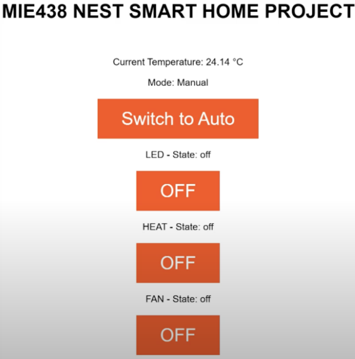
- A responsive HTML web interface was hosted on the ESP32, allowing users to wirelessly monitor temperature and switch between manual and automatic control modes for both the fan and heater.
Mistakes?
A key oversight was the omission of a protection diode between the linear voltage regulator and the ESP32. As a result, when the ESP32 was powered via USB from a laptop while the external 12V power supply was disconnected, reverse current flowed from the microcontroller back into the regulator. This led to damage and eventual failure of the ESP32. Adding a diode would have blocked reverse current and protected the microcontroller in this scenario.
Results?
Key lessons included integrating hardware components and effectively managing power. implemented wireless overrides through a web interface and writing code for different communication protocols.
- Power Management: Using linear regulators and buck convertors to manipulate voltages.
- Wireless Communication: Built an HTML web interface to wirelessly control the Smart Home settings.
- Code for Communication Protocols: writing code for hardware components with different communication protocols.