Designing a Gearbox
The gearbox was a part of the Mechanical Engineering Design, MIE243, course assignment. The purpose of this assignment was to design a gearbox from scratch and use 3D printing to manufacture it. Throughout the fall semester of 2021, we learned to use SolidWorks to either replicate other designs or modify them; this assignment being the last was about the complete engineering process from design to manufacturing. The amount of lessons learned from this project is inconceivable for me.
What did I learn?
- Fast prototyping over perfectionism
- The first prototype never works
- Healthy teamwork leads to great ideas
- I have a strong imagination
- I love being rigorous during idea generation
- I enjoy CAD
Firstly, we started considering various options to achieve a colinear gearbox with a 12:1 ratio. The options included parallel gear design with spur, helical, or herringbone, and also planetary gears. As a group, we decided to go with spur gears due to the limitations we had with SolidWorks Toolbox capability and the time constraint of the assignment.
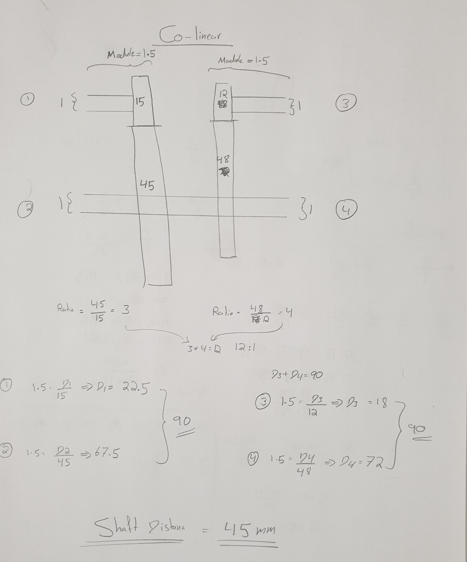 The calculations I did relating to gear ratios, teeth, and centre to centre distance to achieve the colinear design
Then, I began to do various calculations to achieve the specifications we had set. The initial calculations were able to achieve the 12:1 ratio but not the colinear design. However, by doing some iterations and changing teeth numbers I was able to overcome it.
Next, I designed the gears with SolidWorks. SolidWorks has a toolbox feature where gears can be created with specific parameters. When the other team members finished the housing and shaft we began to 3D print our first iteration.
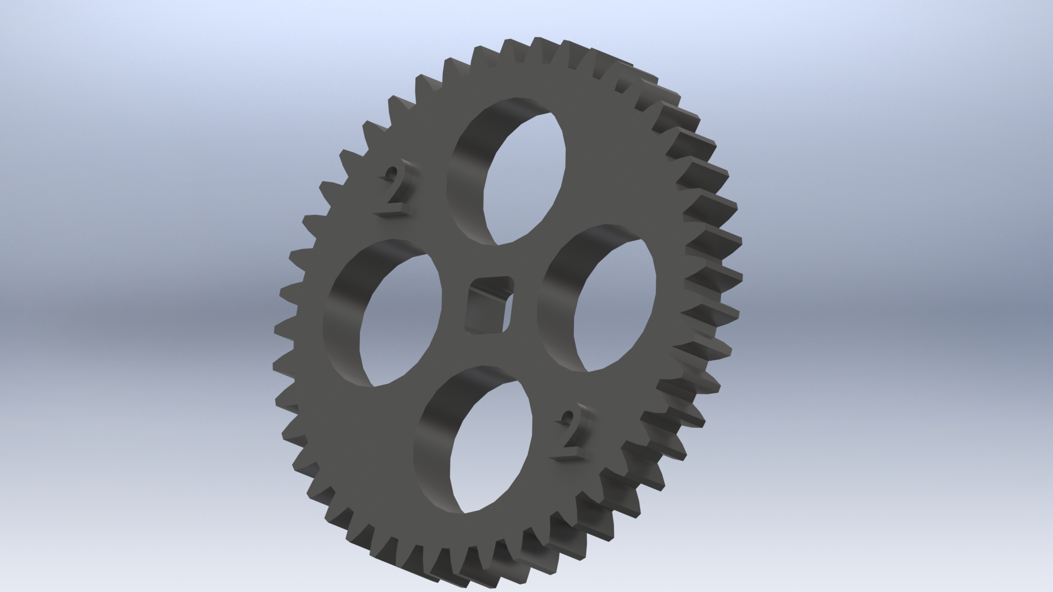 My CAD spur gear design
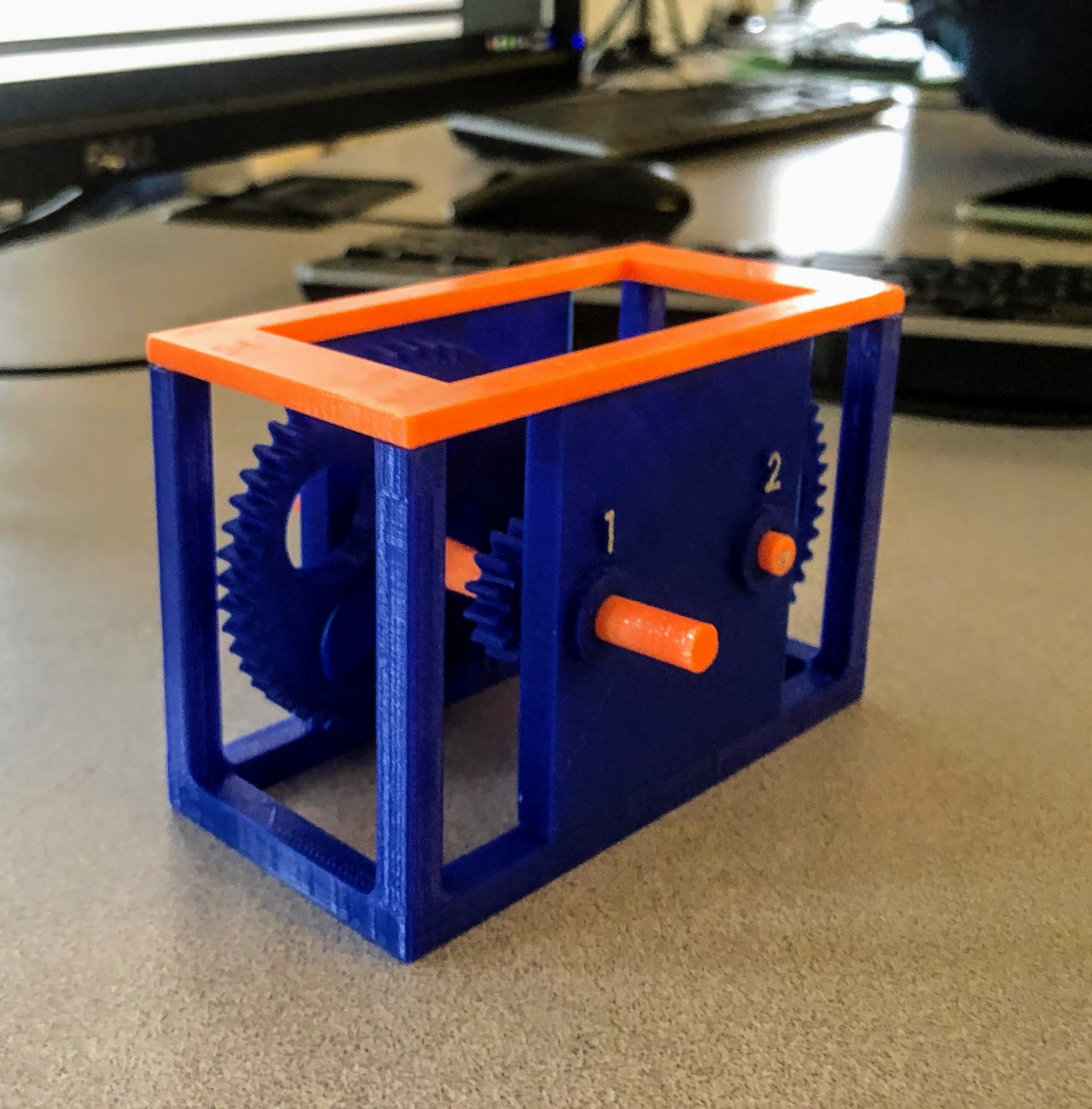
First Iteration:
 First iteration of the gearbox
The first iteration of the gearbox had huge issues. Including:
- The shaft tolerance was too much, this caused the gear to slide over the shaft.
- The components were very small due to scaling the whole design by 60%. We had to do this due to the 6-hour printing constraint.
- Assembly was non-intuitive.
- Design was not colinear due to the wrong calculations I made.
- The shafts were sliding and falling over since there was no restriction
Second Iteration:
 Second iteration of the gearbox
The second iteration solved some issues, however, these issues persisted:
- Too much tolerance and the gear was sliding over the shaft.
- The labeling on the components was not able to print properly since they were to thin.
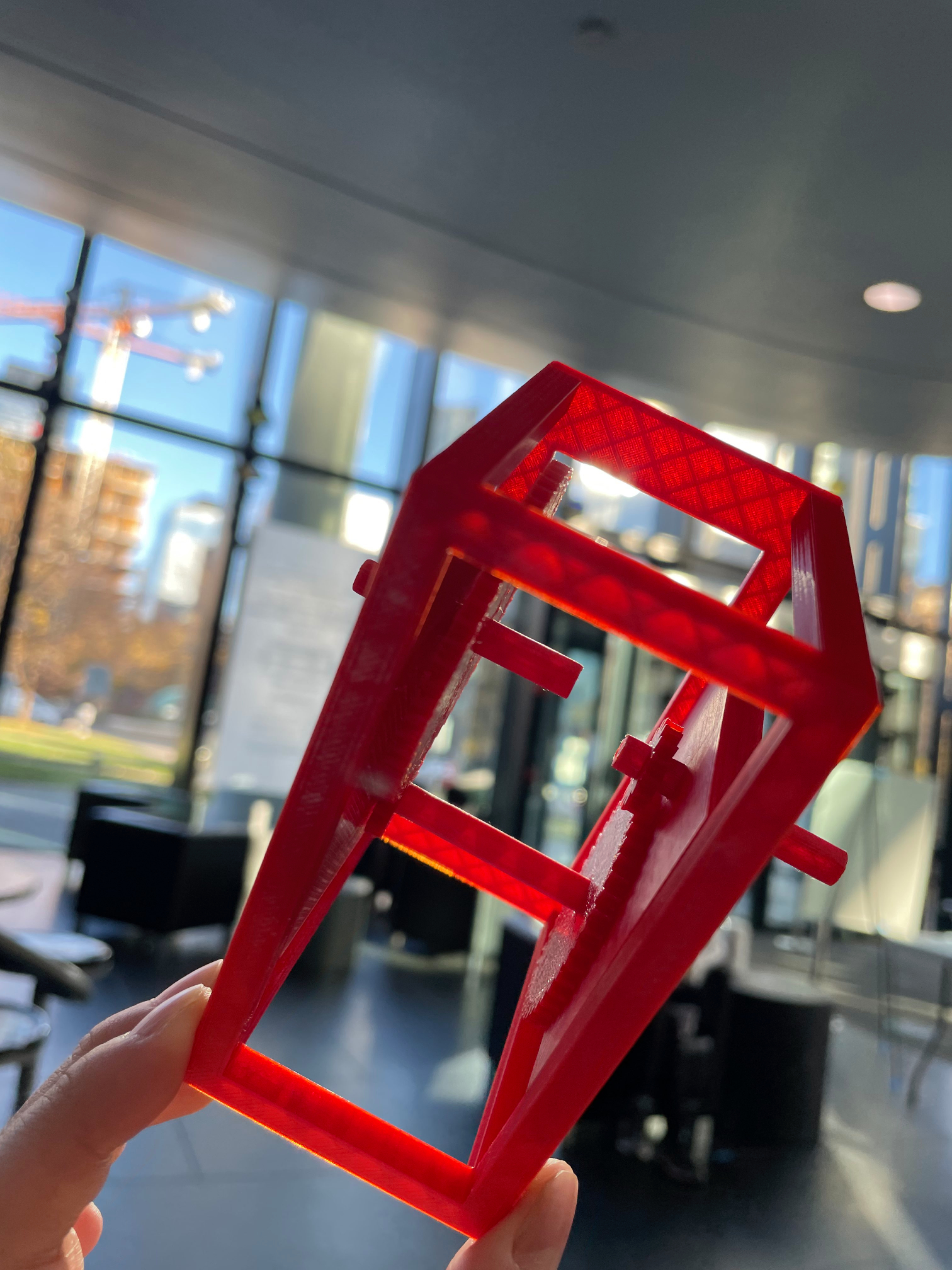
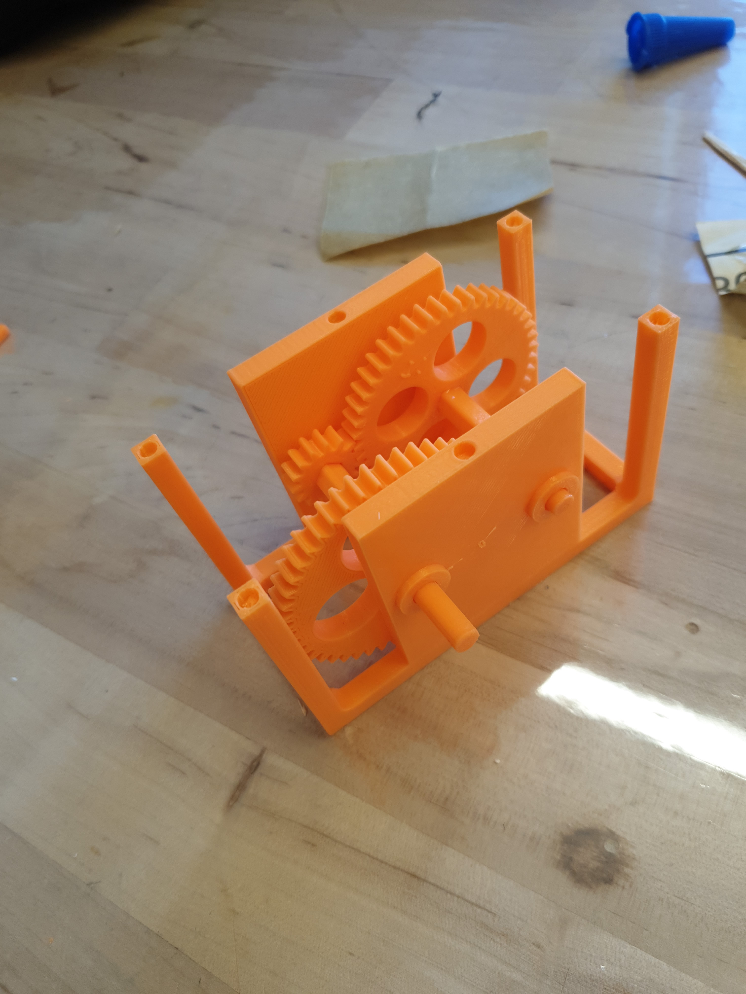
Final Iteration:
Final iteration of the gearbox
This iteration solved almost all the issues. The tolerance was a persistent issue during the other iterations and including this one. Luckily, the shafts from the second iteration were a perfect match for the gears in the final iteration, with some sanding required.
Labeling all the components was my greatest idea. I was able to print all of them during the final iteration. This helped to make the instructions clearer which I will explain later.
IKEA Instructions:
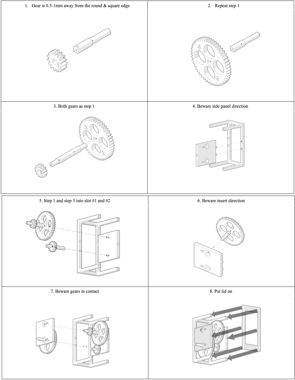 The IKEA instructions using SolidWorks Composer
I handled the full responsibility of creating the assembly instructions. I created the instructions with SolidWorks Composer; a program I had no experience with before this and I was able to learn it in 2 hours. I am very glad how the results turned out for the instructions since it was exactly what the instructors where looking for.
 Youtube Video